The display on our ventilation unit was dead, and one of the two fans had stopped running. The cause was not the main PCB but a corroded capacitor on the outdoor air sensor. A part costing pennies fixed it.
Symptoms
- Front display completely black, green LED on the main PCB lit.
- Errors 1023, 1025, 1027, 1031, 1039, 1041, 1043, 1047, 1049 and 1050, i.e. every temperature and humidity sensor and both flow sensors at once.
- All readings at zero.
- After a restart both fans run for about a minute. Then the errors come back and the unit switches off the fan for the supply air (the fresh air going into the house).
I read the error codes over the ComfoNet bus (CAN) with an ESP32, since the display was not showing anything. On the bus they come without the leading 10, i.e. 23, 25, 27 and so on.
Cause
It was the outdoor air sensor (ODA, the “top” sensor, Zehnder part 400502004). Zehnder lists this possibility themselves: their German fault overview names a possibly defective outdoor air sensor for a display that stays black while the unit is running.
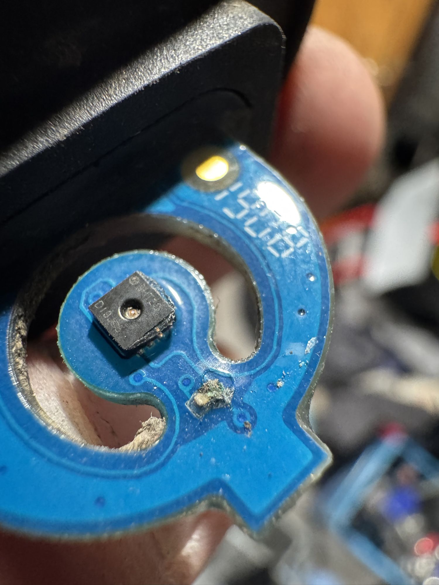
On my unit the small sensor board carries an SHT30 with a capacitor next to it, and that capacitor had corroded. With this sensor plugged in, the communication with the other sensors and with the display was disturbed, so they all went down together. I did not measure how exactly the corrosion caused that.
How to check
The unit should be unplugged from the mains before you touch anything: to avoid damage, and there is 230 V on the board.
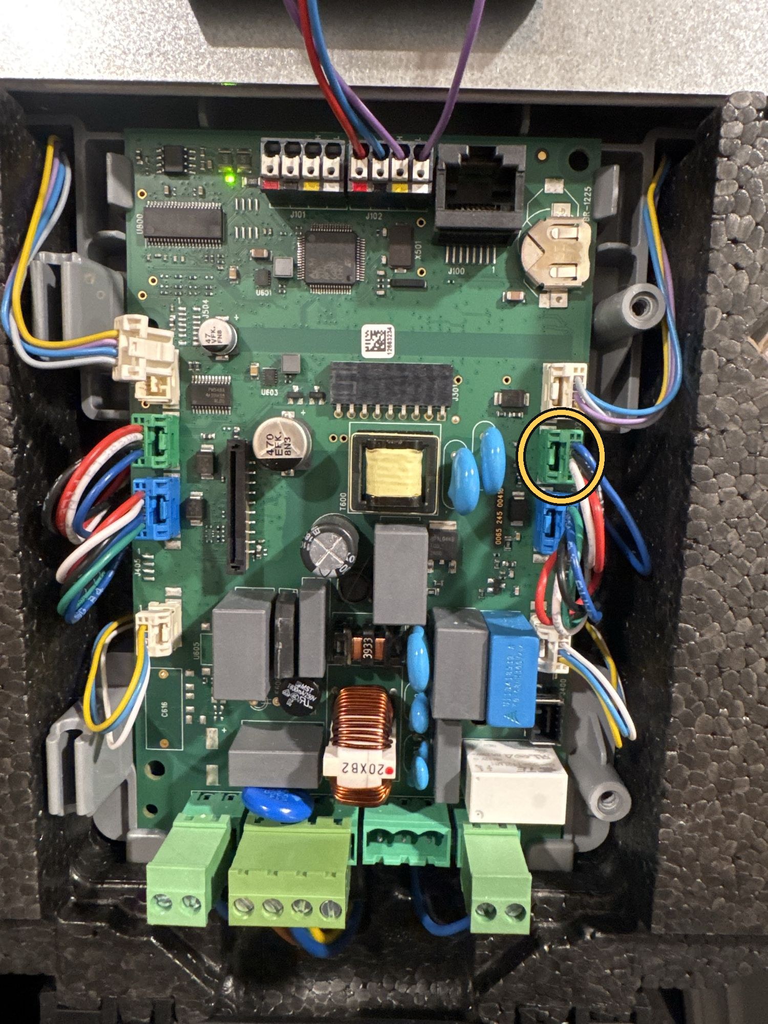
- Unplug the outdoor air sensor at the main PCB. It is one of the two green connectors: the right-hand one if your outdoor air duct is on the right, the left-hand one if it is on the left.
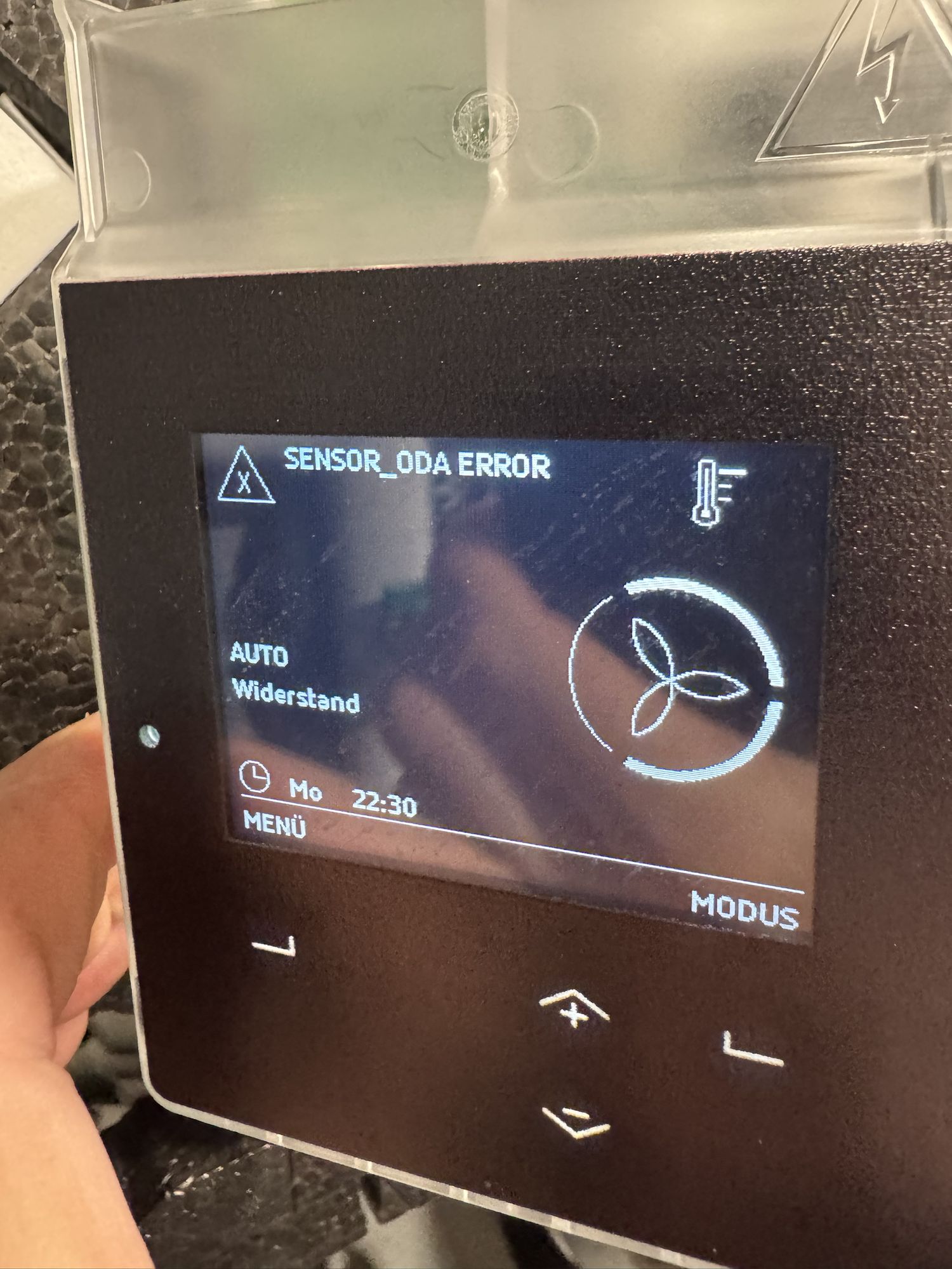
- Power up. If the display comes back, you have found the fault, and the other sensor errors will most likely be gone too. On my unit only
SENSOR_ODA ERROR(1027/1043) remained and the other sensors read normally. - You can’t simply leave it unplugged, though: after power-up both fans start, but as soon as the unit detects the sensor error it switches off the fan for the supply air.
Fix
I pulled the sensor (service manual chapter 6.7: front cover off, heat exchanger out, filters out, pull the sensor down from the inside), desoldered the corroded capacitor and fitted a new 100 nF ceramic one. I damaged a solder pad while removing the old capacitor, so I had to solder in a short wire bridge as well.
I could not read the value off the original part. I assumed it is the chip’s decoupling capacitor, for which the Sensirion SHT3x datasheet specifies 100 nF, and the sensor works with that value. I did not trace where it is actually connected.
With the capacitor merely removed, the display and the other sensors came back but the outdoor air sensor itself did not respond. I don’t know whether it needs the capacitor or whether that was down to the damaged pad. With the new one in place all errors cleared, the display works, and both fans run.
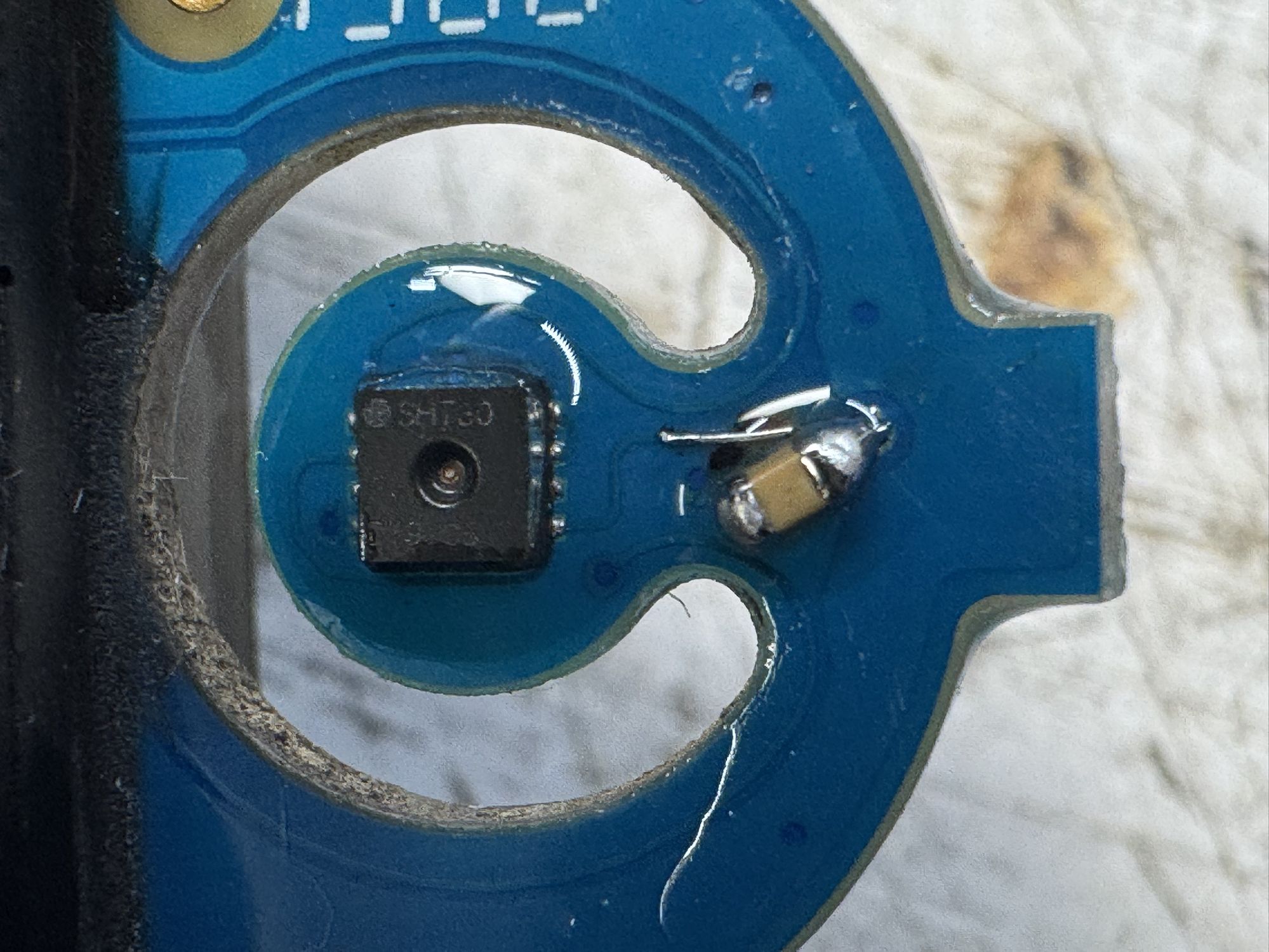
Afterwards I coated the joint and the pins of the sensor with conformal lacquer (CRC Plastik 70), because it is damp in there and the sensor comes lacquered from the factory as well. I applied the lacquer with a pair of tweezers instead of spraying it, so that none of it gets into the SHT30’s sensing opening and clogs the sensor. Masking the opening would probably work too.
If you’d rather not solder
Replacing the complete top sensor is the fix Zehnder recommends.
What matters here is the sensor chip. Older units have an SHT20, newer ones an SHT30; the type is printed on the chip. If you go from an SHT20 to a new sensor with an SHT30, forum reports and dealers say you need a firmware update (1.7.1 or later is the figure given), and on old units an adapter cable set as well. My unit, however, has SHT30 sensors and runs them on firmware 1.7.0; the display shows that version too.
If you only replace the capacitor, you keep your chip and need no update.
Reading it out with an ESP32
Since the display was dead, I read the unit out through its ComfoNet port. ComfoNet is a CAN bus running at 50 kbit/s. Besides CAN-H and CAN-L the port also carries 12 V and ground, so the setup is powered by the unit.
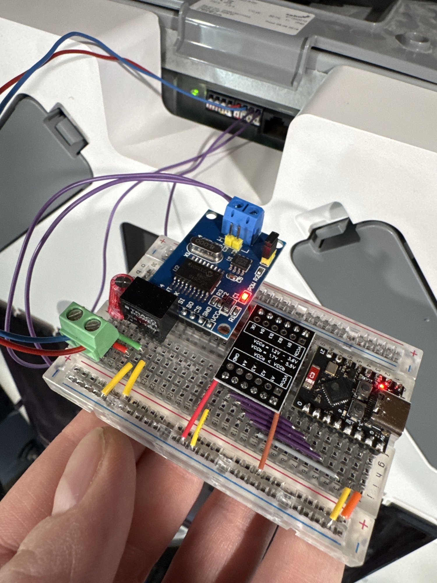
The parts:
- ESP32-C3 Super Mini
- MCP2515 CAN module with TJA1050 and 8 MHz crystal (runs on 5 V)
- TXS0104E level shifter between the ESP (3.3 V) and the MCP2515 (5 V)
- TRACO TSR 1-2450 voltage regulator (12 V to 5 V)
The wiring diagram:
| ESP32-C3 | TXS0104E | MCP2515 |
|---|---|---|
| GPIO 0 | A1 ↔ B1 | SCK |
| GPIO 1 | A2 ↔ B2 | SI (MOSI) |
| GPIO 2 | A3 ↔ B3 | SO (MISO) |
| GPIO 3 | A4 ↔ B4 | CS |
| 3V3 | VCCa and OE | |
| 5V | VCCb | VCC |
12 V and ground come from the ComfoNet terminal and go to the voltage regulator; CAN-H and CAN-L go straight to the screw terminal of the MCP2515 module. The INT output of the MCP2515 is left unconnected. There is also an electrolytic capacitor at the regulator’s 12 V input.
Three things cost me time while getting it to work:
- The MCP2515 has to run in normal mode so that it acknowledges frames. In listen-only mode the unit just repeats the same frame forever.
- I measured about 2 kΩ between CAN-H and CAN-L, so the bus was not terminated. With the 120 Ω jumper on the module it worked.
- I had CAN-H and CAN-L swapped at first.
The ESP runs ESPHome. The configuration reads temperatures, humidity, air flows, fan speeds and the active errors, and offers them as a web interface and to Home Assistant. It can also control the unit: fan level, boost, automatic mode, bypass and temperature profile.
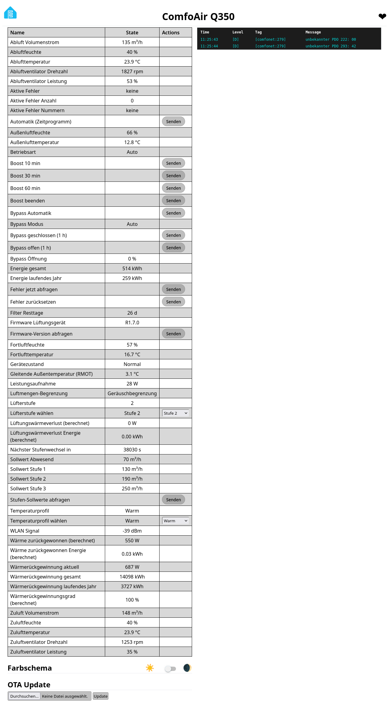
The code to download (comments are in German):
- comfoair.yaml (ESPHome configuration)
- comfoair-web.js (labels the buttons of the web interface)
- secrets.yaml.example (template for WiFi credentials and keys)
Use at your own risk: the control commands interfere with the operation of the unit. The web interface has no password, so anyone on the same network can press the buttons. I only checked the bypass and temperature profile commands against the reference projects and did not try them on the unit.
I did not reverse-engineer the protocol myself. It is based on aiocomfoconnect and comfoair-esp32.
Others with the same fault
- BuildHub forum: a Q350 with a dead display and exactly the same ten error codes; the main PCB was suspected.
- HaustechnikDialog (German): several reports of a corroded capacitor on the ODA sensor; there the sensor was replaced or rebuilt.